

Precision Rectifiers, Absolute value circuits
Objective
The purpose of this experiment is to investigate precision rectifiers or absolute value circuits. Rectifiers, or ‘absolute-value’ circuits are often used as detectors to convert the amplitudes of AC signals to DC values to be more easily measured. For this type of circuit, the AC signal is first high-pass filtered to remove any DC component and then rectified and perhaps low pass filtered.
Notes
In this tutorials we use the terminology taken from the user manual when referring to the connections to the Red Pitaya STEMlab board hardware. Oscilloscope & Signal generator application is used for generating and observing signals on the circuit. Extension connector pins used for -3.3V and +3.3V voltage supply are show in the documentation here.
Materials
- Red Pitaya STEMlab
- 1x OP484 quad rail-rail op-amp
- 5x 10 kΩ Resistors
- 2x small signal diodes (1N914 or similar)
Background
As we have seen in the simple rectifier circuits constructed with diodes, the circuit does not respond well to signals with a magnitude less than a diode-drop (0.7V for silicon diodes). This limits their use in designs where small amplitudes are to be measured. For designs in which a high degree of precision is needed, op-amps can be used in conjunction with diodes to build precision rectifiers.
The inverting op-amp circuit can be converted into an “ideal” (linear precision) half-wave rectifier by adding two diodes as shown in figure 2. For the negative half of the input diode D1 is reverse biased and diode D2 is forward biased and the circuit operates as a conventional inverter with a gain of -1. For the positive half of the input, diode D1 is forward biased, closing the feedback around the amplifier. Diode D2 is reverse biased disconnecting the output from the amplifier. The output will be at the virtual ground potential ( - input terminal ) through the 10kΩ resistor.
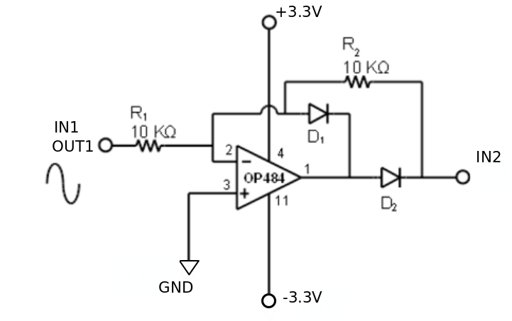
Figure 1: Connection diagram for precision half-wave rectifier
Procedure
- Build the circuit from figure 1 on the breadboard
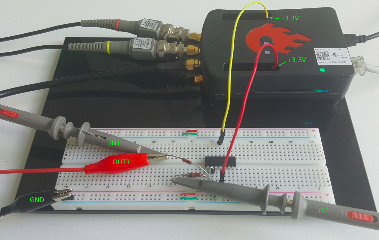
Figure 2: Connections on the breadboard
- Start the Oscilloscope & Signal generator application
- In the OUT1 settings menu set Amplitude value to 0.5V, DC offset to 0.1 V, Frequency to 100Hz to apply the input voltage. From the waveform menu select SINE, deselect SHOW and select enable.
- On the left bottom of the screen be sure that IN1 and IN2 V/div are set to 200mV/div (You can set V/div by selecting the desired channel and using vertical +/- controls
- Set t/div value to 2ms/div (You can set t/div using horizontal +/- controls)
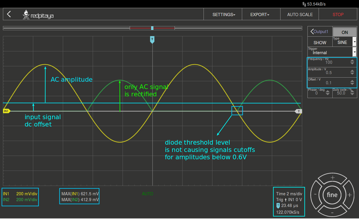
Figure 3: Precision half-wave rectifier measurements
Note
From the measurements shown on picture 3 we can observe following: The peak of the rectified output should now equal to the peak value of the input (only AC peak, note that DC level of the input signal is not transfered to the output). There is also a sharp transition as the input crosses zero. The experimenter should investigate the waveforms at different points in the circuit to explain why this circuit works better than the simple diode half wave rectifier.
For this experiment you should:
- Try to change OUT1 DC offset and amplitude and observe results.
- Study the circuit and determine how it works. There is a very fundamental concept that should help in understanding how this circuit operates. Given an op-amp configured with negative feedback, the inverting and non-inverting input terminals will try to reach the same voltage level, often referred to as a “virtual ground.
- Plan some tests to see if this circuit indeed is a rectifying circuit. Perform these tests, fully documenting all tests and results in your lab report.
- Carefully measure and record voltages at all nodes in the circuit.
Questions
- What happens if the direction of the diodes is reversed? Repeat experiment with the direction of both diodes reversed.
Full wave rectifier
We can modify the half wave rectifier to make full wave rectifier or absolute value circuit. The circuit shown in figure 4 is an absolute value circuit, often called a precision full-wave rectifier. It should operate like a full wave rectifier circuit constructed with ideal diodes ( the voltage across the diode, in forward conduction, equals 0 volts). The actual diodes used in the circuit will have a forward voltage of around 0.6 V.
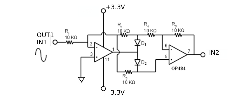
Figure 4: Precision full-wave rectifier
Procedure
- Build the circuit from figure 4 on the breadboard
Warning
Before connecting the circuit to the STEMlab -3.3V and +3.3V pins double check your circuit. The -3.3V and +3.3V voltage supply pins do not have short circuit handling and they can be damaged in case of short circuit.
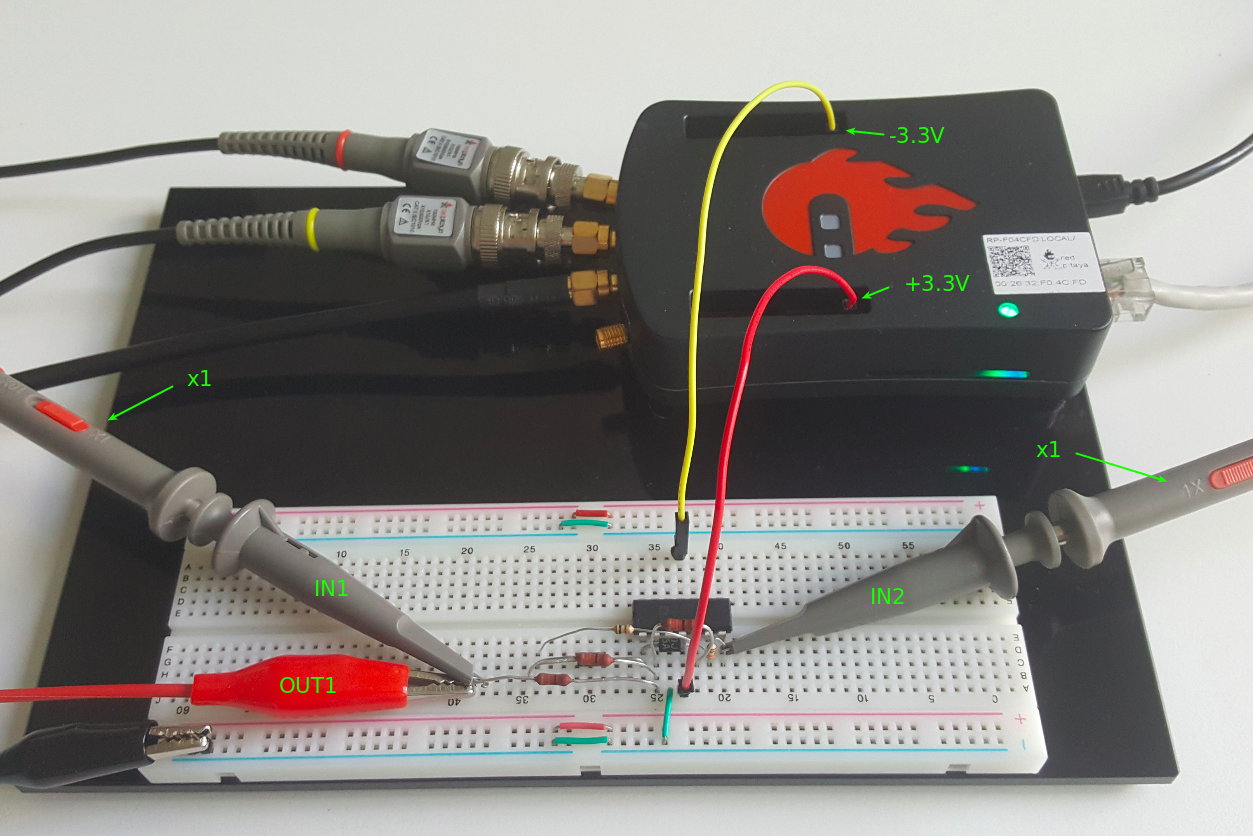
Figure 5: Connections on the breadboard
- Start the Oscilloscope & Signal generator application
- In the OUT1 settings menu set Amplitude value to 0.5V, DC offset to 0.1 V, Frequency to 100Hz to apply the input voltage. From the waveform menu select SINE, deselect SHOW and select enable.
- On the left bottom of the screen be sure that IN1 and IN2 V/div are set to 200mV/div (You can set V/div by selecting the desired channel and using vertical +/- controls
- Set t/div value to 2ms/div (You can set t/div using horizontal +/- controls)
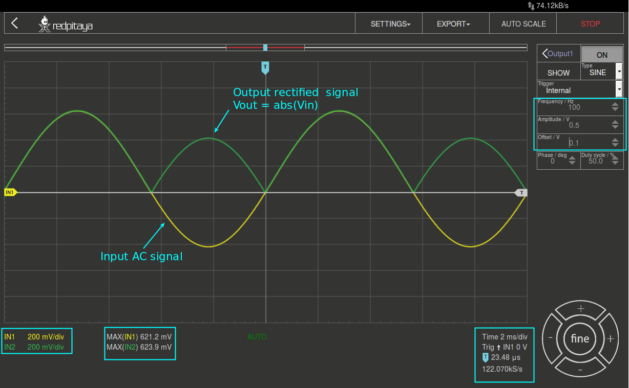
Figure 6: Precision full-wave rectifier measurements - Absolute value circuit
Note
As we can see from the figure 6 the circuit shown on figure 4 is indeed a full wave rectifier where diode threshold voltages are NOT causing any affects as it is case in diode rectifiers. Also we can see that DC offset value is not excluded from the rectifying process making this circuit a absolute value circuit.The name absolute value circuit comes from the fact that, as we can see from the figure 6, the output signal (IN2) is an absolute value of the input signal (IN1).
Questions
- What happens if the direction of the diodes is reversed? Repeat experiment with the direction of both diodes reversed.
- What happens if the direction of one diode is opposite of the other? Repeat experiment with the direction of one diode (D1) reversed.